Call us now :08045478310

 Send Inquiry
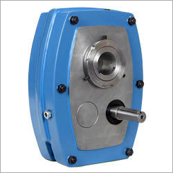
Iron Metal Shaft Mounted Speed Reducer
MOQ : 1 Unit
Iron Metal Shaft Mounted Speed Reducer Specification
- Usage
- Industrial
- Material
- Iron
- Processing Type
- Hobbing
- Size
- Standard
- Product Type
- Shaft Mounted Speed Reducer
- Color
- Blue
- Voltage
- 220-240 Volt (v)
Iron Metal Shaft Mounted Speed Reducer Trade Information
- Minimum Order Quantity
- 1 Unit
- Payment Terms
- Cash Advance (CA)
- Supply Ability
- 1000 Units Per Month
- Delivery Time
- 7 Days
- Main Domestic Market
- All India
About Iron Metal Shaft Mounted Speed Reducer
Based on technologically advanced designs, our Shaft Mounted Speed Reducer caters to the needs of varied output speeds.We offer it at affordable price.
The Jimi's Shaft Mounted Speed Reducer provides a very easy technique of decreasing speed, since it is mounted directly on the driven shaft in the place of needing foundations of its own. It eliminates the utilization of one and sometimes two flexible couplings as well as external belt take-up arrangements.
A torque-arm anchors the Reducer and offer fast, simple adjustment of the V-Belts with the help of its turnbuckle. The Optigear Speed Reducer is fabricated in eight gear case sizes, developed by the letters B to H. The eight sizes may have anyone of three common gear ratios 5:1, 13:1 and 20:1.
A very broad choice of last driven speed can be determined by using of an appropriate input V -Belt drive. The units are generally oil lubricated, but they are proportionally suitable for lubricated for life" greases.
Selection Procedure:
(1) Service Factor - From T able 1 select the service factor applicable to the drive.
(2) Design Power - Multiply the absorbed power (or motor power if absorbed power not known) by the service factor chosen in step (1).
Note: Ensure that design power exceeds motor rated power.
(3) Peak Load - Divide any peak load by two.
(4) Unit Selection - Using the greater value of steps (2) and (3) refer to the Power Rating Tables and select the correct size of unit. The choice of single or double reduction gearbox will be determined by the output speed required The normal operating speeds for each of the gearboxes may be observed in the Power Rating Tables. For other speeds CONSULT OPTIGEAR.
Note: 5.1 Units require special selection when fitted with backstops CONSULT OPTIGEAR
Selection of Associated Drive for 1440 rev/min Electric Motors
(5) Output Speed - Refer to the Drive Selection Tables and under the appropriate gearbox size and ratio read down the column headed 'Output Speed' until an output speed equal or near to that required is found
TABLE - SERVICE FACTORS
| Types of Driven Machine | Operational Hour Per Day | ||
| Under 10 | 10 to 16 | 16 and over | |
| Uniform | 1.0 | 1.12 | 1.25 |
| Moderafe Shock | 1.0 | 1.12 | 1.25 |
| Heavy Shock | 1.6 | 1.8 | 2.0 |
(6) Pulley Diameters - Read across from the chosen output speed to obtain both driving and driven pulley pitch diameters and the appropriate number of belts.
(7) Centre Distance - Belt length and centre distance can be found by referring to pages 2 & 4 of Wedge Belt catalogue.
Selection of Associated Drive for Driving Speeds other than 1440 rev/min
(8) Design Power - Obtain from the Power Rating Tables the rated power of the gearbox at the required output speed and use it as the design power for the drive
(9) Gearbox Input Shaft Speed - Multiply the gearbox output speed by the exact gear ratio to obtain the gearbox input shaft speed
(10) Selection of V-Drive - Combination of pulleys can be chosen It is advisable not to select a gearbox pulley smaller than that shown in the drive tables for the approximate speed required.
Specifications:
| Model | Rating At 40rmp 13(KW) 20:1 Ratio | Rating At 200rmp (KW) 5:1 Ratio | Height (mm) | Width (mm) | Depth (mm) | Standard Hub Bore (mm) | Alternative Hub Bore (mm) | Approx. Mass Kg. 20:1 | 320 No. Oil Required Oil Limit |
| B | 1.05 | 2.99 | 226 | 186 | 134 | 30 | 40 | 17.00kg. | 1.5 to 2 ltr |
| C | 1.70 | 4.41 | 270 | 218 | 142 | 40 | 50 | 23.00kg. | 1.5 to 2 ltr |
| D | 2.84 | 7.26 | 328 | 258 | 152 | 50 | 55 | 34.00kg. | 2.5 to 3 ltr |
| E | 4.36 | 10.80 | 377 | 278 | 170 | 55 | 60 | 45.00kg | 3.5 to 4 ltr |
| F | 6.85 | 15.50 | 414 | 317 | 189 | 65 | 70 | 72.00kg | 5 to 5.5 ltr |
| G | 10.80 | 26.60 | 468 | 365 | 212 | 75 | 80 | 97.00kg | 7.5 to 8 ltr |
| H | 16.90 | 38.10 | 550 | 434 | 242 | 85 | 90 | 146.00kg | 10.5 to 11 ltr |
| J | 26.30 | 92.00 | 700 | 542 | 257 | 100 | 105 | 270.00kg. | 21 to 22 ltr |
| Model | Conveyors Belt Sixes of Shaft Mounted Gear Box |
| D | 18" belt with x length 20ft, 30ft, 40ft, 50ft |
| E | 24" belt width x length 30ft, 40ft, 50ft, 60ft |
| F | 30" belt width x length 30ft, 40ft, 50ft, 60ft |
| G | 36" belt width x length 30ft, 40ft, 50ft, 60ft, 70ft, 80ft, 100ft |
| H | 48" belt width x lenth 40ft, 60ft, 70ft, 80ft, 1000ft |
| J | 60" belt width x length 40ft, 60ft, 80ft, 100ft, 150ft. |
Tell us about your requirement

Price:
Quantity
Select Unit
- 50
- 100
- 200
- 250
- 500
- 1000+
Additional detail
Mobile number
Email

More Products in Automotive Gearbox Category
Our Products
- Automotive Axles
- Automotive Gears
- Automotive Shafts
- Earthmoving Equipment Spares
- Commercial Vehicle Gears & Shafts
- Gears & Shafts for Jeep
- Automotive Engine Parts
- Axles for 2 Wheelers
- Pivot Pins
- Automobile Bushing
- 2 Wheeler Engine Parts
- JCB Spares
- Spur Gears
- 3 Wheeler Gears
- Speed Reducer
- Right Angle Gear Box
- Transmission Gears
- Bevel Gears
- LCV Gears
- Automotive Gearbox


C-64, Mayapuri Industrial Area, Phase-II,New Delhi - 110064, India

Mr. Jasdeep Singh Kalsi
(CEO)
Mobile :08045478310
 Send Inquiry
 Send SMS
Developed and Managed by Infocom Network Private Limited.
